
Learn how to control Tone Value Increase (TVI) across prepress and pressroom units. Understand the difference between mechanical squeeze and optical light scattering to hit ISO 12647 tolerances. For certified industrial production, calibrate pressroom settings in alignment with ISO 12647 offset process control standards and Idealliance G7 grayscale calibration standard.
Understanding Dot Gain: Mechanical vs. Optical Tone Value Increase
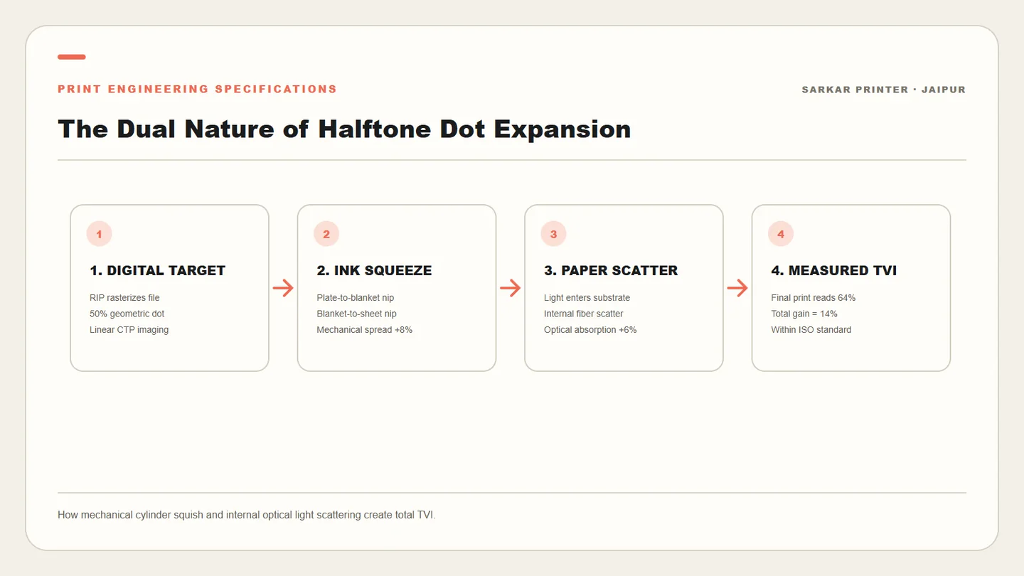
In offset lithography, dot gain—formally termed Tone Value Increase (TVI)—occurs when halftone dots print larger on the final paper sheet than their intended area on the digital file. A 50% checkerboard tint on the computer monitor that reproduces as 66% on printed paper has experienced a 16% dot gain. If dot gain goes unmanaged, images look muddy, midtone contrast collapses, and dark shadow details plug into solid black. Dot gain stems from two distinct physical phenomena: mechanical dot gain and optical dot gain. Mechanical dot gain occurs in the physical press nip as viscous ink spreads under hydraulic cylinder pressure and blanket shear. Optical dot gain occurs inside the paper fibers themselves; light penetrates the paper surface, scatters internally beneath the edges of the ink dot, and is absorbed, making the dot appear visually larger to human eyes and spectrophotometers. Align color management targets with Idealliance G7 grayscale calibration standard.
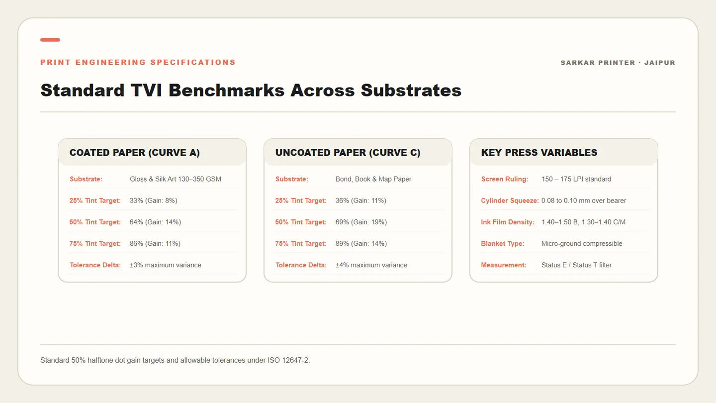
ISO 12647-2 Tone Value Curves: Standard Tolerances for Coated and Uncoated Stock
Because physical ink expansion is inevitable, international printing standards do not seek zero dot gain; rather, they establish predictable, repeatable target curves. Under ISO 12647-2 (the benchmark standard for sheetfed offset lithography), target dot gain curves are defined by substrate category. For premium coated art paper (Curve A), the standard TVI target at the 50% halftone patch is 14% (resulting in an effective 64% measured tint). For uncoated woodfree offset paper (Curve C), higher porosity and fiber spread shift the target 50% gain to 19% (reading 69% on the densitometer). To achieve compliant production, modern prepress departments linearize their Computer-to-Plate (CTP) thermal laser imagers using compensation curves. If press calibration reveals a raw 50% dot printing at 70% on coated stock (a 6% excess over target), the CTP RIP curve intentionally burns a 44% dot onto the aluminum plate, ensuring the finished press sheet hits the exact 64% ISO target. Verify production tolerances against ISO 12647 offset process control standards.
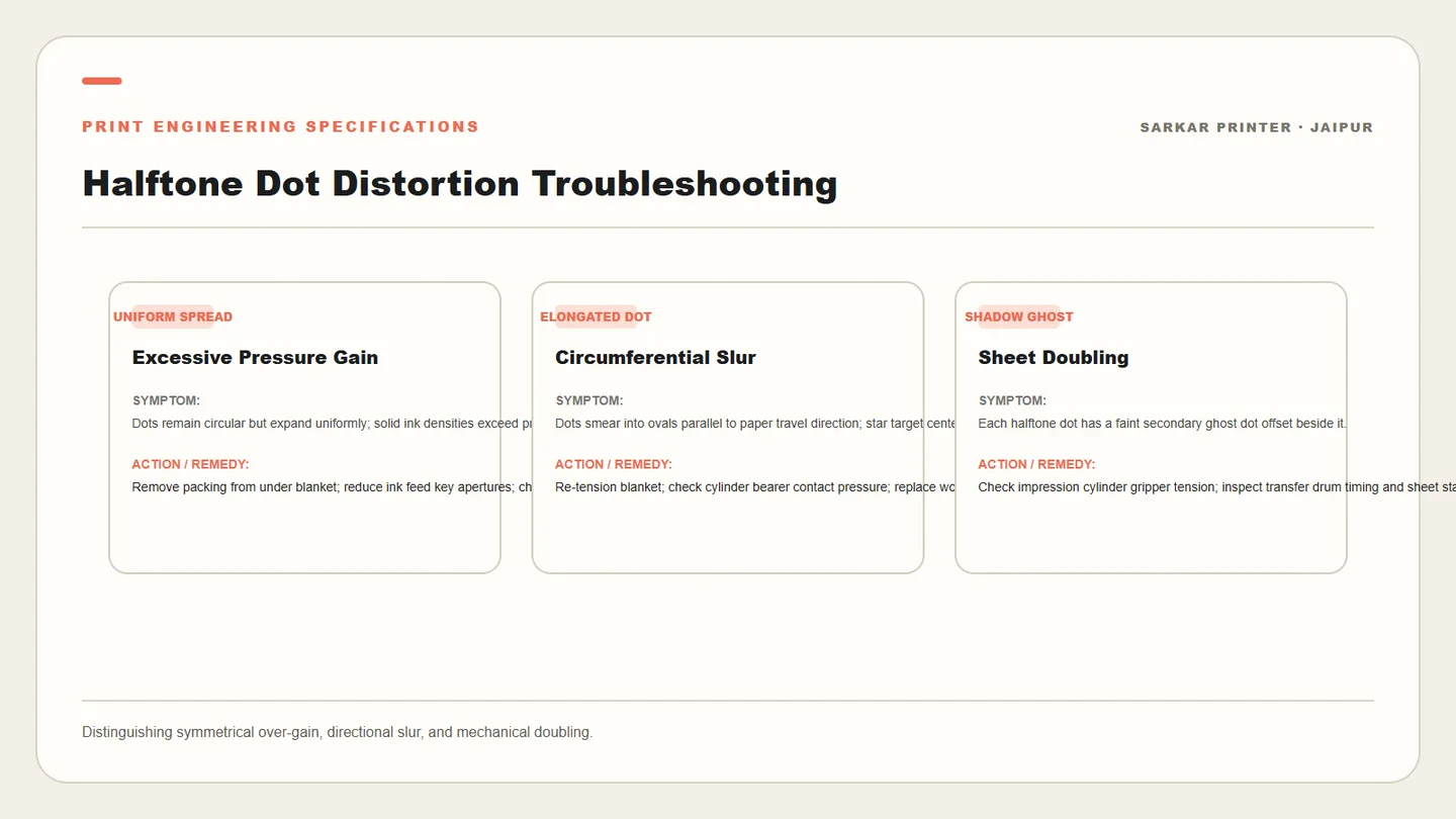
Pressroom Causes of Excess Dot Gain: Slur, Doubling, and Pressure
When a press run experiences abnormal dot gain outside ISO tolerances, press operators must inspect three core pressroom mechanical variables: cylinder packing pressure, ink viscosity, and directional slurring. Excessive cylinder squeeze between blanket and impression cylinders physically squashes ink droplets outward. Directional slurring occurs when blanket surface velocity does not match plate surface velocity, smearing dots into micro-ellipses along the direction of cylinder rotation. "Doubling" happens when ink transfer from a previous sheet remains on the blanket and offsets out of register onto the following sheet due to gripper play or cylinder gear backlash. Use circular Star Targets and Slur Strips on the trim edge of the sheet to distinguish symmetrical pressure dot gain from directional mechanical slurring.
Standard Calibration Protocol: Fingerprinting the Pressroom
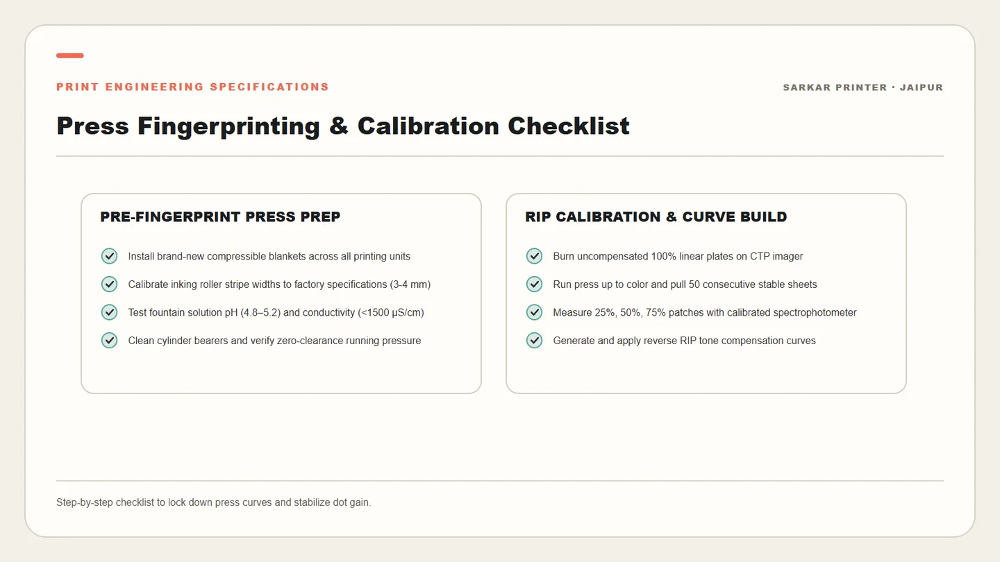
Eliminating dot gain surprises requires performing a formal "Press Fingerprint" every six months. Print an uncorrected, 100% linear CTP test form across your primary production paper stocks at standard solid ink densities. Measure 10-step tonal scales across all four printing units using a calibrated spectrophotometer. Import the measured data into your prepress RIP software to construct customized compensation curves. By marrying linear CTP plates with empirical press calibration curves, prepress files automatically compensate for press mechanical characteristics, guaranteeing flawless reproduction on every commercial run.
Frequently asked questions
Why does higher screen ruling (LPI) cause higher dot gain?
Higher screen rulings (such as 200 LPI vs 133 LPI) require significantly smaller halftone dots to represent the same percentage tint. Because smaller dots have a far higher ratio of perimeter edge to total surface area, the capillary spread of ink around dot borders creates a much higher percentage increase in total area.
How does ink tack affect dot gain on a multi-color press?
In multi-color printing, ink tack must follow a descending sequence: Black (highest tack) -> Cyan -> Magenta -> Yellow (lowest tack). If downstream colors have higher tack than upstream colors, they pluck previously laid wet ink off the paper and onto the blanket, destabilizing dot geometry.
What is the Murray-Davies formula?
The Murray-Davies formula is the classic mathematical equation used by densitometers to calculate dot area from reflection density values: $Dot\% = \frac{1 - 10^{-(D_t - D_0)}}{1 - 10^{-(D_s - D_0)}} \times 100$, where $D_t$ is tint density, $D_s$ is solid density, and $D_0$ is unprinted paper density.
CONTINUE THE PRINT PLAN
Plan Your Commercial Print Project in Jaipur
From precision multi-color offset runs to high-end rigid luxury boxes and folding cartons, Sarkar Printer delivers certified color accuracy and structural integrity for businesses across India.